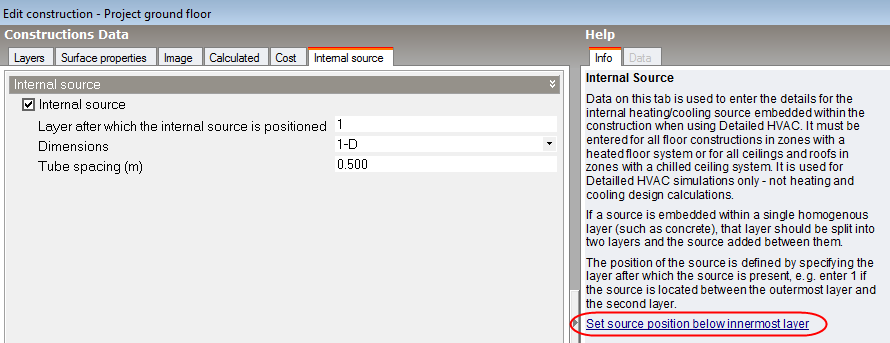
Internal Source tab on Constructions Dialog.
The internal source tab is visible only when the model is set to use Detailed HVAC. It allows data on the position and nature of any heating or cooling pipes included within the construction. Internal sources are associated with one of these components:
Check this option if the construction includes a heating or cooling source.
Enter a number between 1 and 1-the number of layers. Entering 1 means that the source is positioned between the outermost layer and the next layer. If you are defining a heated floor construction then you will normally enter 1-the number of layers. The easiest way to do this is to use the Set source position below innermost layer tool described below. When defining a chilled ceiling as a floor construction you should enter a value of 1 here.
Important Note: The internal source must be placed thermally closer to the inside surface than to the outside surface of the construction to allow it to be considered for inclusion in a zone's radiant surface, heated floor or chilled ceiling system. In other words, if the thermal resistance between the inside surface and the internal source is less than the resistance to the outside surface then the surface is considered to be a valid radiant surface to be included with the zone next to the inside surface and will be simulated as such. This rule applies to surfaces adjacent to outside as well as internal surfaces.
This field refers to the detail level of the calculation. Select from the 2 options below for a 1-D or 2-D solution:
Note: Because the 1-D solution method does not allow the return water temperature to be accurately calculated it is not recommended for when accurate plant energy consumption outputs are required. In this case choose the 2-D option.
The 2-D solution method generally takes about 20% longer to run a simulation relative to the 1-D option.
This field defines how far apart (in m or in) the hydronic tubing are spaced in the direction perpendicular to the main direction of heat transfer. This parameter is used when either the 1-D or 2-D Dimension setting is selected (above).
A tool is provided in the info panel when using learning mode which calculates which is the innermost layer and adds the source between this and the next layer. For example in a chilled ceiling construction you might have 0.5 mm steel ceiling panel as the innermost layer with 3 other layers. In this case when clicking on the Set source position below innermost layer link, the innermost layer value would be set to 3.
Note: Constructions with an internal source cannot be used in ground surfaces which are adjacent to a Kiva Foundation. You can use surfaces with an internal source in any other surface in Kiva simulations though.