Radiant Surface Data
Radiant surfaces allow you to model a wide range of radiant systems where water is passed through pipes in a panel or embedded in the construction, transferring energy to/from a building surface (wall, ceiling or floor). They can be used to model low-temperature heated only surfaces (e.g. heated floors), cooled only surfaces (e.g. chilled ceilings) or changeover systems which heated or chilled water is passed through pipes to provide heating or cooling depending on the zone load. They can also be used to simulate surfaces with buried electric heating elements.
See the Radiant surfaces tutorial
Three types of radiant surfaces are available in DesignBuilder HVAC:
Note an important advantage of the EnergyPlus variable flow radiant surface over the constant flow equivalent is that it is fully autosizable, which makes it much quicker to set up, especially for large models.
When using the 2-Detailed HVAC Detailed HVAC Activity data option, radiant surface systems will only control based on the radiant system controls defined for the component itself and not via the standard zone thermostat defined on the HVAC zone dialog. If the radiant system is serving a zone with forced air equipment, the radiant system will follow the priority order established by the zone thermostat but will still base its response on the controls defined by the user for the radiant system.
When using the 1-Simple HVAC Detailed HVAC Activity data option, radiant surfaces are controlled using the usual HVAC zone heating setpoint temperature controls.
Note: In zones in which radiant systems are included, at least one surface must be assigned a construction with an internal source defined, which incorporates details of the embedded tubing system. See Internal Source under Constructions for further details.
Radiant surface HVAC components are placed, edited and deleted at HVAC zone level. To edit the data associated with a radiant surface, you first need to select it by moving the mouse cursor over it and then clicking the mouse button to select it. You can then access the edit dialog by right-clicking the mouse and selecting the Edit selected component option or alternatively, select the Edit selected component tool from the toolbar.
Important Note 1: The internal source must be placed thermally closer to the inside surface than to the outside surface of the construction to allow it to be considered for inclusion in a zone's radiant surface system. In other words, if the thermal resistance between the inside surface and the internal source is less than the resistance to the outside surface then the surface is considered to be a valid radiant surface to be included with the zone next to the inside surface and will be simulated as such. This rule applies to surfaces adjacent to outside as well as internal surfaces.
Important Note 2: Internal radiant surfaces cannot control heating/cooling delivery to both adjacent zones. The radiant surface will be associated with the control system of the adjacent zone that is thermally closest to the internal source. The zone next to the outside surface (thermally furthest from the internal source) will of course still receive some heating/cooling from the source but the heat flow will generally be less and it will not be controlled.
Tip: To define which side of an internal surface is internal and which is external see under Layer order on the Constructions Layer data page.
Heated Floors
These systems typically use low flow temperatures of around 40-55°C compared with around 80°C for traditional low temperature hot water heating systems using radiators and convectors. Lower return temperatures enable more efficient operation using condensing boilers and heat pumps.
Tip: Heated floor radiant surfaces can be connected to hot water loops fed by boiler, GSHP or district heating systems. Note that when connected to GSHP systems heated floors can offer a very efficient system as the low delivery temperatures they require (typically 35°C) are well matched to the optimal operating conditions for GSHP systems.
 Troubleshooting Heated Floors
DesignBuilder EnergyPlus can realistically model heated floor systems and so many of the issues that apply to real systems such as slow response, floor mass, control, floor insulation, effect of different upper surface materials can be investigated using DesignBuilder. However heated floors can take a little bit of care to set up and to achieve good temperature control. If you are having trouble with this you may find the answer to the problem is the list below.
- Missing Internal Source Error report. Each zone with a heated floor added to its HVAC zone must include at least one floor surface (or floor sub-surface) having a construction with an internal source. If no such internal source surface is found, DesignBuilder will generate an error message to this effect before attempting to run the simulation.
- Unresponsive control. Heated floor systems have relatively slow response times as the heating pipes provide indirect heating via the floor surface. This can result in zone temperatures deviating from set-point temperatures if the heating or cooling loads in the zone change quickly, through solar gain or natural ventilation cooling for example. The slow response is due to the high thermal mass of the floor causing heat to continue to be emitted even when the room thermostat has stopped calling for heating and the pump has stopped moving hot water through the embedded pipes. Overheating in such high mass heated floors can be a common problem on days where a high demand exists on a cold morning (for example) but then high solar (or other) gains in the day add to the uncontrolled heat continuing to be emitted from the floor.
- Throttling range. Less of a factor than point 2 is variable flow heated floors work using a throttling range to control flow of water through the embedded floor water pipes. This acts like a deadband and means that even without the thermal mass lag issues, there will be a temperature control range rather than a fixed zone temperature.
- Underheating can also be a common issue with heated floors. Likely causes are listed below.
- Large heat loss. A useful rule of thumb is that it is not usually possible to supply more than about 100 W/m2 of heating with heated floors due to the thermal resistance of floor surfaces and maximum acceptable floor temperatures of around 29°C, though higher surface temperatures are possible in bathrooms. Typical maximum outputs are approximately 100 W/m2 for concrete, reducing to 70 W/m2 for timber floors and less for carpet and coverings with insulating properties. Zones having higher levels of heat loss will require supplementary heating to achieve comfortable conditions. This is true of real world systems and with DesignBuilder EnergyPlus heated floor models. The easiest way to check the heat loss against this rule is by using the Normalise display option which shows results per floor area.
- Intermittent heating. Running heated floors on an intermittent basis requires a higher design sizing factor to be set for the HVAC zone. This is because of the thermal mass of the floor construction. Consider a building unoccupied over a cold weekend which then needs to be heated to operating temperatures on Monday morning. With the default sizing factor of 1.25 the heating system will have been sized to achieve the heating setpoint under steady-state winter outdoor design condition plus a margin of 25%. However this 25% margin will not be adequate if the heating is to switched on at say 6am and expected to raise the zone temperature to comfortable levels in time for occupancy a few hours later. To deal with intermittent operation, either much higher design factors are required (e.g. 2) or the system should be run continuously (perhaps at a lower level during unoccupied periods) to avoid the need for a rapid warmup in the mornings. Of course if the heating is to be operated continuously the building fabric will need to be very well insulated to avoid waste.
- Incorrect position of the source. A common error with setting up the heated floor definition is to select the wrong position for the heated floor source (i.e. the hot water pipes). In a well designed system the pipes will normally be buried just below the first construction layer. If you position the tubes at the wrong side of the construction, then the wrong zone (or the ground or exterior) will be heated! A tool is provided on the Constructions dialog to make it easy to position the source just below the innermost layer.
- Conductive upper layer. Heated floors provide the most efficient and responsive control when the uppermost layer is low mass and conductive. While ceilings can be constructed using a thin metal layer between source and the room, this is rarely possible for heated floors which are required to provide a strong and comfortable surface to walk on as well as an efficient heat transfer path from heating pipes to the zone. Clearly, if the top layer is an (insulating) thick pile carpet then the heated floor will struggle to provide adequate heating to the room. More advice on floor coverings suitable for heated floors is provided below.
- Insulation. Without good insulation below the heated floor source, much of the heat will not find its way into the intended zone. Instead the heat will be either lost to the zone below in an uncontrolled way, to outside or to the ground. There will consequently be less heat available to heat the intended zone and underheating will occur.
- Sizing error (general HVAC modelling issue). It is important to consider heating and cooling sizing when setting up schedules. In particular, a common mistake is to include internal gains in heating sizing calculations. This has the effect of heating being undersized causing significant underheating (or no heating).
- When used in combination with a chilled ceiling in zone below, heated floors will cause EnergyPlus to generate an error. This is because EnergyPlus only allows one "source" object per surface and so a heated floor cannot be located in the same surface as a chilled ceiling. There are 2 possible workarounds to this.
- Export the DesignBuilder model to EnergyPlus and using the IDF Editor combine the heated floor and chilled ceiling into a single source component.
- Insert a very thin "dummy zone" between the heated floor above and the chilled ceiling below. Include half of the true floor mass in the upper surface (heated floor in upper zone) and the other half in the lower surface (chilled ceiling in lower zone).
- You may need a separate high-grade heat generator for DHW if using a low-temperature heat source for heating.
Tip: To help diagnose some of the above problems and to check that maximum temperatures are compatible with the surface material (below) it can help to view hourly inside and outside surface temperatures and heat fluxes by selecting these output options: Surface heat transfer incl. solar (gives heat flux for floors) or Inside surface temperature (to check the surface temperature of the heated floor).
Coverings Suitable for Heated Floors
The advice in this section has been adapted from www.nu-heat.co.uk.
Stone and ceramic surfaces
From the thermal point of view, the best floor coverings for use with underfloor heating are usually hard surfaces such as stone and ceramic tile as they have the least thermal resistance allowing heat from the pipe array to transfer quickly to the surface of the stone/tile.
- Ceramic tiles - Due to their high thermal conductivity and slim profile, ceramic tiles are one of the best floor finishes for use with underfloor heating.
Timber flooring and underfloor heating
Engineered timber is the best of the wooden floor options for use with underfloor heating as its structural stability allows it to perform well with fluctuating temperatures. Solid hardwoods and soft woods also transfer heat well but care should be taken when specifying board width and thickness.
- Engineered timber - The best timber floor finish for use with heated floors, offering good heat transfer and structural stablity.
- Solid hardwood - Good heat transfer and best when specified in narrow board widths.
- Softwood - Suitable only in narrow board widths to reduce movement
- Parquet - Offers good heat transfer when securely glued to the sub-floor
- Bamboo - Usually similar in construction to engineered timber, making it very suitable for UFH
Laminates, vinyl and rubber
Laminates and vinyl floor coverings also perform well with underfloor heating. It is advisable to check the manufacturer’s recommended maximum floor surface temperature to ensure the product is suitable for use with UFH. Most manufacturers state an upper limit of 27˚C, which equates to approximately 75W/m2 of heat output, which is adequate in most situations. These products have low thermal mass so heat up and cool down quickly in comparison to stone and timber.
- Vinyl - good heat transfer, often subject to a recommended maximum surface temperature
- Amtico - practical, high-quality finish that transfers heat well
- Linoleum & Marmoleum - thin natural products that are suited to use with underfloor heating
- Laminate tiles - Thin and thermally conductive making them perfect for use with UFH
- Rubber - A relatively thermally conductive material that can successfully be used with underfloor heating
Materials to avoid
While not ideal from the efficiency point of view, carpet and underlay with a combined Tog value of up to 2.5 can be used effectively with underfloor heating. Thicker carpets act as an insulator and stop sufficient heat reaching the room.
- Carpet - A maximum Tog value of 2.5 is recommended for carpet and underlay when used with underfloor heating
- Cork - A maximum thickness of 10mm is advised as cork is an efficient insulator
- Coir - A natural product similar to carpet that is subject to a maximum recommended Tog value of 2.5
You should bear in mind that some flooring manufacturers stipulate a maximum floor temperature for their product. Note also that EN 1264 states that underfloor heating should not operate at more than 29˚C.
Chilled Ceilings
Chilled ceilings are mounted within the ceiling to provide quiet, draft free cooling of the space below. Each unit is made up of a small bore chilled water pipe arranged in an S-shape and attached to the upper surface of a ceiling panel. Ceiling panels are typically of thin metallic construction but can simply be plasterboard. In some systems the chilled water pipes are embedded within the ceiling panel.
During operation, the panel is cooled through contact with the chilled-water pipework allowing it to cool the space through a combination of convective and radiant output (up to 40% radiant). An insulating mat is often placed above the chilled water pipework and panel to minimise uncontrolled cooling of the area above. It is up to the user to include any such insulation in the construction definition.
One advantage of chilled ceilings is that they can be placed in a shallow ceiling void enabling them to be used in buildings with low floor to ceiling heights. However, their limited cooling output makes them unsuitable for areas with moderate to high heat gains. The maximum capacity of chilled ceiling systems is in the order of 70 W/m2.
Chilled-ceiling systems require a separate ventilation system for fresh air supply.
Condensation of room air on and within the chilled ceiling can be avoided by shutting of chilled water flow based on room dew point temperature.
Tip: Chilled ceilings can be connected to chilled water loops fed by chillers , district cooling or GSHP systems.
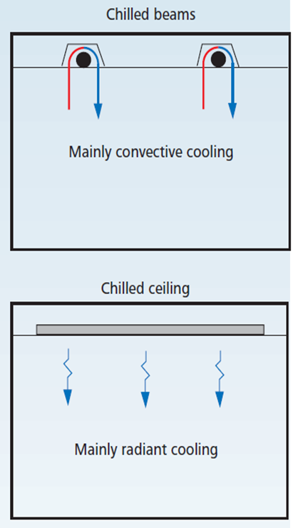
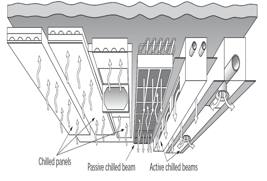
Chilled ceilings vs Cooled beams
The images below (reproduced with permission from CIBSE) illustrate the difference between the cooled beams described here and chilled ceilings.
CIBSE KS03 Figure 12
CIBSE Guide H Fig 5.79
Tip: A useful resource on chilled ceilings and cooled beams can be found at https://www.feta.co.uk/uploaded_images/files/CBCA/Chilled%20Beams%20Brochure_Final%207%20%28web%29.pdf
Troubleshooting Chilled Ceilings
The DesignBuilder EnergyPlus ceiling model is able to realistically model the operation of chilled ceiling systems and many of the issues that apply to real systems such as intermittency, thermal mass, control, ceiling insulation, effect of different interior surface materials can be investigated using DesignBuilder. However chilled ceilings can take a little bit of care to set up and to achieve good temperature control. If you are having trouble with this you may find the answer to the problem is the list below.
- Missing Internal Source Error report. Each zone with a chilled ceiling added to its HVAC zone must include at least one ceiling surface (or ceiling sub-surface) having a construction with an internal source. If no internal source surface is found, DesignBuilder will provide an error message to this effect before attempting to run the simulation.
- Unresponsive control. Chilled ceilings in real buildings tend to give less responsive control than air or other radiant systems. This is because the relatively high thermal mass of the ceiling causes zone heat to continue to be absorbed even when the room thermostat has stopped calling for cooling and the pump has stopped moving chilled water through the embedded pipes.
- Throttling range. Less of a factor than point 2 is variable flow chilled ceilings work using a throttling range to control flow of water through the embedded floor water pipes. This acts like a deadband and means that even without the thermal mass lag issues, there will be a temperature control range rather than a fixed zone temperature.
- Inadequate cooling can also a common issue with chilled ceilings. Likely causes are listed below.
- High levels of internal gains. A useful rule of thumb is that it is not usually possible to supply more than about 70 W/m2 of cooling with chilled ceilings. Zones having higher levels of gains will require supplementary cooling to achieve comfortable conditions. This is true of real world systems and with DesignBuilder EnergyPlus chilled ceiling models. The easiest way to check the internal gains against this rule is by using the Normalise display option which shows results per floor area.
- Intermittent cooling. Running chilled ceilings on an intermittent basis can require a higher design sizing factor to be set for the HVAC zone. This is because the thermal mass of the ceiling construction causes a lag in cooling provided to the coils and cooling provided to the room. Consider a building unoccupied over a warm weekend which then needs to be cooled to operating temperatures on Monday morning. With the default sizing factor of 1.15 the cooling system will have been sized to achieve the cooling setpoint under "periodic steady-state" summer design condition plus a margin of 15%. However this 15% margin will not be adequate if the cooling is to switched on at say 6am and expected to lower the zone temperature to comfortable levels in time for occupancy a few hours later. To deal with intermittent operation, either much higher design factors are required (e.g. 2) or the system should be run continuously (perhaps at a lower level during unoccupied periods) to avoid the need for a rapid cooling down in the mornings. Of course if the cooling is to be operated continuously then the building fabric will need to be very well insulated to avoid waste.
- Incorrect position of the source. A common error with setting up the chilled ceiling definition is to select the wrong position for the chilled ceiling source (i.e. the chilled water pipes). In a well designed system the pipes will normally be buried just below the first construction layer. If you position the tubes at the wrong side of the construction, then the wrong zone (or the ground or exterior) will be cooled! A tool is provided on the Constructions dialog to make it easy to position the source just above the innermost layer.
- Conductive lower layer. Chilled ceilings provide the most efficient and responsive control when the uppermost layer is low mass and conductive. Chilled ceilings panels are often constructed using a thin metal layer between source and the room to provide an efficient heat transfer path from cooling pipes to the zone. Clearly, if the inside layer is an (insulating) ceiling tile for example then the chilled ceiling will struggle to provide adequate cooling to the room.
- Insulation. Without good insulation above the chilled ceiling source, much of the cooling will not find its way into the intended zone. Instead the cooling will be either lost to the zone above in an uncontrolled way, to outside or to the ground. There will consequently be less cooling available to cool the intended zone and under-cooling will occur.
- When used in combination with a heated floor in zone above, chilled ceilings will cause EnergyPlus to generate an error. This is because EnergyPlus only allows one "source" object per surface and so a chilled ceiling cannot be located in the same surface as a heated floor. There are 2 possible workarounds to this.
- Export the DesignBuilder model to EnergyPlus and using the IDF Editor combine the heated floor and chilled ceiling into a single source component.
- Insert a very thin "dummy zone" between the heated floor above and the chilled ceiling below. Include half of the true floor mass in the upper surface (heated floor in upper zone) and the other half in the lower surface (chilled ceiling in lower zone).
Tip: To help diagnose some of the above problems it can help to view hourly inside and outside surface temperatures and heat fluxes by selecting these output options: Surface heat transfer incl. solar (gives heat flux for floors) or Inside surface temperature (to check the surface temperature of the chilled ceiling).
Heated Floor above Chilled Ceiling
In some cases it may be necessary to model a heated floor heating a zone above with a chilled ceiling on the same surface cooling a different zone below. However, EnergyPlus does not allow more than one internal source per surface, so in this case it would be necessary to create a fictitious zone between the 2 surfaces allowing the heated floor and chilled ceiling to be created in their respective zones and to be controlled individually. and satisfying the requirement of no more than one internal source per surface. Note that the restrictions referred to above apply equally to radiant surfaces used to model heated floors and chilled ceiling as to the specific heated floor and chilled ceiling components.
Target Tab
When editing the attributes associated with a radiant surface component it is possible to apply the same changes to units in other zones in the same HVAC Zone group. To do this select the components on the Target tab of the edit dialog as required.