Block and Zone Dimensions
WARNING: THIS TOPIC REFERS TO V3 AND HAS NOT YET BEEN UPDATED
See: Geometry Areas and Volumes
Combined constructions
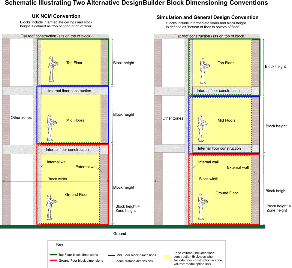
The diagram below illustrates how blocks should be defined and how zone
volumes and surface dimensions are derived from the parent block when
using the default Combined
constructions model option. Note that there are 2 alternative dimensioning protocols:
- UK NCM Convention which should always be used when using DesignBuilder for assessing buildings through the UK National Calculation Methodology, i.e. for Part-L and Section 6 Building Regulations checks and EPC/BER calculations.
- Simulation and General Design Convention which should generally be used for all other applications where an NCM calculation is not required.
The main differences between the 2 conventions are:
- UK NCM Convention - For ground and intermediate floors, the block height is defined as "top of floor to top of floor" and for top floor blocks with a flat roof the block height is "top of floor to soffit/underside of roof slab". Details on defining building geometry for other less common geometries when using the NCM can be found in the Non Domestic EPC Conventions for England & Wales document.
- Simulation and General Design Convention - For ground floors the block height is "top of floor to bottom of floor". For intermediate floors, the block height is defined as "bottom of floor to bottom of floor" and for top floor blocks with a flat roof the block height is "bottom of floor to soffit/underside of roof slab".
The important points to note for both conventions are:
- The length/width dimensions of the block are measured
from the outside of external walls.
- Zone height is always the same as block height, i.e. it is unaffected by block wall thickness or thickness of floor constructions.
- Wall surfaces extend the full height of the block.
- Flat roofs are placed on top of the block, so
when drawing a block with a flat roof you should exclude the roof
construction in the height.
- External floors are placed under the block, so
when drawing a block with an external floor you should exclude the external floor construction thickness
in the height.
- Zone surface dimensions (shown in green dotted
lines above) are measured from inner edges of outer walls and the centre
line of partitions.
- Floor surfaces extend horizontally to the inner
surface of external walls and to the centre line of partitions. See below
for more on zone/surface dimensions.
 Show
diagram for Separate Constructions
Show
diagram for Separate Constructions
For Separate constructions the volume of the zone is calculated as the floor area x the block height. The volume of any floor and ceiling voids and associated constructions can be subtracted if the relevant model options are checked.
The zone volume used in ventilation
calculations is the actual inside volume (shown in yellow in the diagram
above). These inside zone surface dimensions are used to define surface
heat transfer areas in simulations and other calculations.
Zone perimeter (plan view)
Other related information
- See Combined
Constructions for information on the meaning of the Construction Model
data.
- Also see Constructions
for how to edit the construction configuration.
- Block wall thickness for information on how zone inner volumes are created from external block dimensions
- Construction and glazing model options for details of volume calculations with the options to include/exclude floor and ceiling volumes from the zone volume used in the energy calculations.
- And the Model
Geometry Example section for a detailed worked example illustrating
how surface areas and volumes are calculated.
 The Creating a model Tutorial
