![]() ZoneHVAC:LowTemperatureRadiant:VariableFlow
ZoneHVAC:LowTemperatureRadiant:VariableFlow
Used in:
- HVAC Zones
|
|
|
Used in:
|
The constant flow chilled ceiling keeps flow rate constant via a local circulation pump and varies the water temperature that is sent to the ceiling. This is accomplished with a mixing valve that is controlled by a sensor. The constant flow chilled ceiling type has a built-in local secondary loop. It will re-circulate flow coming out of the system and mix this with flow from the loop to arrive at the desired inlet temperature to the ceiling (note that this chilled ceiling model has the temperature sensor after the pump to ensure proper inlet temperature to the ceiling). The local loop also contains a pump which is assumed to be upstream of the component and after the mixing valve. So, the local loop can have some recirculation. The flow from the main loop may also bypass the component if more than enough flow is available and the main loop is also a constant flow system.
This is a read-only label that is automatically generated by the software and which incorporates the name of the zone in which the chilled ceiling is located.
There are 3 ways to define the cooling capacity of the unit as selected from the following list of options:
This autosizable field defines the convective electric nominal cooling capacity (in W or Btu/h). It is only available when the Cooling design capacity method is set to 1-Design capacity.
Enter the cooling capacity per unit floor area (in W/m2 or W/ft2) of the unit. This data is only available when the Cooling design capacity method is 2-Capacity per floor area.
The program calculates the cooling capacity from floor area of the zone served by the unit and the cooling capacity per unit floor area value specified here.
Enter the cooling capacity as a fraction of the autosized cooling capacity for convective electric baseboard unit. This data is only available when the Cooling design capacity method is 3-Fraction of autosized capacity. EnergyPlus calculates the cooling capacity from the design autosized cooling capacity and this fraction. The default value is 1.0.
There are two types of chilled ceiling available:
This is the inside diameter (in m or in) of the tubes through which water is circulated. The inside diameter is used to determine the convective heat transfer from the water to the inside surface of the hydronic tubing.
This is the total length of embedded pipe (in m or ft). The length of the tube is used to determine the effectiveness of heat transfer from the fluid being circulated through the tubes and the tube/surface. Longer tubing lengths result in more heat that will be transferred to/from the radiant surface to the circulating fluid.
Note: With the constant flow chilled ceiling, this length is not autosizable.
This input allows you to choose between modelling each surface in the radiant system as a single hydronic circuit or to allow the program to divide the surface into multiple parallel hydronic circuits based on the Circuit length (below). The corresponding options are:
It is recommended that 2-Calculate from circuit length be chosen for new models. The default is 1-One per surface for backward compatibility with older versions of DesignBuilder.
The length (in m or ft) of each parallel hydronic circuit in a surface. This data is only used when the Number of circuits (above) is set to 2-Calculate from circuit length. The default is 106.7 meters (350 feet), which is the maximum circuit length allowed in Title 24.
This is the maximum flow rate of water through the chilled ceiling (in m3/s or gal/min). This flow rate is held constant by the local component pump, but you have the option of varying this flow rate via a schedule (see Pump flow rate schedule below). The constant flow system will accept this flow rate and control the inlet temperature based on the control and water temperature schedules defined below.
This schedule modifies the maximum flow rate of water through the chilled ceiling (in m3/s only). Note that the values for this schedule must be between zero and one.
This is the pump rated head (Pa or ftH20).
This is the pump rated power consumption (W).
This is the pump efficiency in decimal form (0 = 0%, 1 = 100%).
This is the fraction of the pump power lost to the fluid.
This option is only available when using the 2-Detailed HVAC Detailed HVAC Activity data
Along with setpoint (control) and water schedules, this setting allows you to specify how the chilled ceiling is to be controlled. The temperature denoted in the setpoint schedule can refer to one of five different temperatures: the zone mean air temperature, the zone mean radiant temperature, the zone operative temperature, the outdoor dry-bulb temperature, or the outdoor wet-bulb temperature. The choice of temperature is controlled by the temperature control type. Select from the following options:
Operative temperature for chilled ceiling controls is the average of Mean air temperature and Mean radiant temperature. See the control temperature schedule settings below for more information.
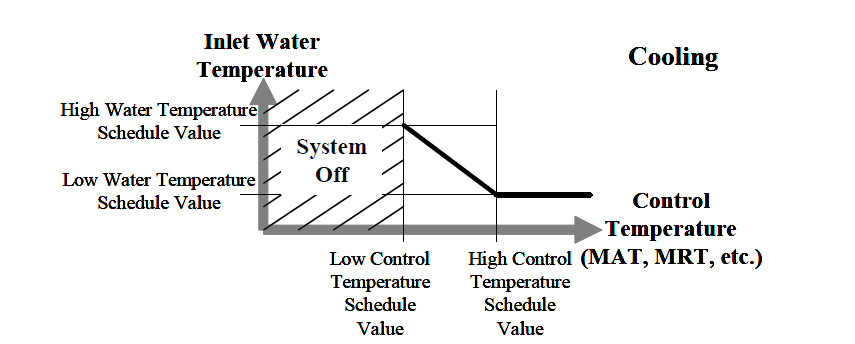
This schedule specifies the high water temperature (in °C only) for the temperature control of a constant flow chilled ceiling. Water and control temperatures for cooling work together to provide a linear function that determines the water temperature sent to the chilled ceiling. The current control temperature (see Temperature control type above) is compared to the high and low control temperatures at the current time. If the control temperature is above the high temperature, then the inlet water temperature is set to the low water temperature. If the control temperature is below the low temperature, then system will be turned off and the water mass flow rate will be zero. If the control temperature is between the high and low value, then the inlet water temperature is linearly interpolated between the low and high water temperature values.
This schedule specifies the low water temperature (in °C only) for the temperature control of the constant flow chilled ceiling. For more information on its interpretation, see Cooling high water temperature schedule above.
This schedule specifies the high control temperature (in °C only) for the temperature control of a constant flow chilled ceiling. For more information on its interpretation, see Cooling high water temperature schedule above.
This schedule specifies the low control temperature (in °C only) for the temperature control of a constant flow chilled ceiling. For more information on its interpretation, see Cooling high water temperature schedule above.
With a chilled ceiling, there is the possibility that condensation will occur on the surface that is being cooled. This is due to the fact that the surface temperature may drop below the dew-point temperature of the space. When this occurs, condensation on the surface will occur. There are two options for handling this situation:
If you choose the 2‑Off option, EnergyPlus will not do anything other than produce a warning message when condensation is predicted to occur. The simulation will simply proceed; no moisture will be removed from the zone air and there will be no adjustment of the surface temperature as a result of the condensation. When the 1‑Simple off option is selected, EnergyPlus will predict cases where condensation will occur and shut-off the chilled ceiling to avoid this situation. With this latter option, you also have the opportunity to adjust when the system will shut down. This is specified with the Condensation Control Dew-point Offset, below.
This offset temperature (in °C or °F) is only valid with the 1-Simple off condensation handling algorithm (see Condensation control type above). It establishes the difference between the calculated dew-point temperature of the space and the allowed surface temperature to which the surface can drop before the chilled ceiling shuts down. This setting can be any positive, negative, or zero value. When this parameter is zero, the chilled ceiling will shut down when the surface temperature drops to the dew-point temperature or below.
When this parameter is positive, the radiant system will shut down when the surface is this value above the dew-point temperature. This allows some extra safety to avoid condensation. When this parameter is negative, the chilled ceiling will shut down when the surface temperature is this value below the dew-point temperature. While not recommended, this strategy allows the user to simulate a situation where small amounts of condensation are tolerable.
Note: This value is an offset not an absolute temperature. A typical value might be 0-2°C.
This schedule that denotes whether the component can run during a given hour. A schedule value greater than 0 (usually 1 is used) indicates that the unit is available and can be on during the hour. A value less than or equal to 0 (usually 0 is used) denotes that the unit is not available and must be off for the hour.