Chilled Ceiling
Chilled ceilings are mounted within the ceiling to provide quiet, draft free cooling of the space below. Each unit is made up of a small bore chilled water pipe arranged in an S-shape and attached to the upper surface of a ceiling panel. Ceiling panels are typically of thin metallic construction but can simply be plasterboard. In some systems the chilled water pipes are embedded within the ceiling panel.
During operation, the panel is cooled through contact with the chilled-water pipework allowing it to cool the space through a combination of convective and radiant output (up to 40% radiant). An insulating mat is often placed above the chilled water pipework and panel to minimise uncontrolled cooling of the area above. It is up to the user to include any such insulation in the construction definition.
One advantage of chilled ceilings is that they can be placed in a shallow ceiling void enabling them to be used in buildings with low floor to ceiling heights. However, their limited cooling output makes them unsuitable for areas with moderate to high heat gains. The maximum capacity of chilled ceiling systems is in the order of 70 W/m2.
Chilled-ceiling systems require a separate ventilation system for fresh air supply.
Condensation of room air on and within the chilled ceiling can be avoided by shutting of chilled water flow based on room dew point temperature.
Tip: Chilled ceilings can be connected to chilled water loops fed by either chillers or GSHP systems.
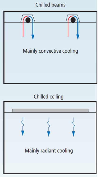
Chilled ceilings vs Cooled beams
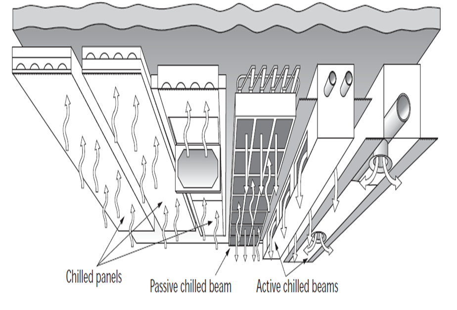
The images below (reproduced with permission from CIBSE) illustrate the difference between the cooled beams described here and chilled ceilings.
CIBSE KS03 Figure 12
CIBSE Guide H Fig 5.79
Two types of chilled ceiling are available in DesignBuilder HVAC:
Note one advantage of the EnergyPlus variable flow chilled ceiling over the constant flow chilled ceiling is that it is fully autosizable.
When using the Detailed HVAC activity option, chilled ceilings will only control based on the radiant system controls defined for the component and not via a zone thermostat such as is used for forced air systems. If the radiant system is serving a zone with forced air equipment, the radiant system will follow the priority order established by the zone thermostat but will still base its response on the controls defined by the user for the radiant system.
When using the Simple HVAC activity option, chilled ceilings are controlled using the usual HVAC zone cooling setpoint temperature controls.
Important Note: At least one ceiling/roof construction in zones in which chilled ceilings are included must have a special internal source construction which incorporates details of the embedded tubing system. See Internal Source under Constructions for further details.
Chilled ceiling HVAC components are placed, edited and deleted at HVAC zone level. To edit the data associated with a chilled ceiling, you first need to select it by moving the mouse cursor over it and then clicking the mouse button to select it. You can then access the edit dialog by right-clicking the mouse and selecting the Edit selected component option or alternatively, select the Edit selected component tool from the toolbar.
Tip: A useful resource on chilled ceilings and cooled beams can be found at http://www.feta.co.uk/uploaded_images/files/CBCA/Chilled%20Beams%20Brochure_Final%207%20%28web%29.pdf
Target Tab
When editing the attributes associated with a Chilled ceiling it is possible to apply the same changes to units in other zones in the same HVAC Zone group. To do this select the components on the Target tab of the edit dialog as required.
Troubleshooting Chilled Ceilings
The DesignBuilder EnergyPlus ceiling model is able to realistically model the operation of chilled ceiling systems and many of the issues that apply to real systems such as intermittency, thermal mass, control, ceiling insulation, effect of different interior surface materials can be investigated using DesignBuilder. However chilled ceilings can take a little bit of care to set up and to achieve good temperature control. If you are having trouble with this you may find the answer to the problem is the list below.
- Missing Internal Source Error report. Each zone with a chilled ceiling added to its HVAC zone must include at least one ceiling surface (or ceiling sub-surface) having a construction with an internal source. If no internal source surface is found, DesignBuilder will provide an error message to this effect before attempting to run the simulation.
- Unresponsive control. Chilled ceilings in real buildings tend to give less responsive control than air or other radiant systems. This is because the relatively high thermal mass of the ceiling causes zone heat to continue to be absorbed even when the room thermostat has stopped calling for cooling and the pump has stopped moving chilled water through the embedded pipes.
- Throttling range. Less of a factor than point 2 is variable flow chilled ceilings work using a throttling range to control flow of water through the embedded floor water pipes. This acts like a deadband and means that even without the thermal mass lag issues, there will be a temperature control range rather than a fixed zone temperature.
- Inadequate cooling can also a common issue with chilled ceilings. Likely causes are listed below.
- High levels of internal gains. A useful rule of thumb is that it is not usually possible to supply much more than about 70 W/m2 of cooling with chilled ceilings. Zones having higher levels of gains will require supplementary cooling to achieve comfortable conditions. This is true of real world systems and with DesignBuilder EnergyPlus chilled ceiling models. The easiest way to check the internal gains against this rule is by using the Normalise display option which shows results per floor area.
- Intermittent cooling. Running chilled ceilings on an intermittent basis can require a higher design sizing factor to be set for the HVAC zone. This is because the thermal mass of the ceiling construction causes a lag in cooling provided to the coils and cooling provided to the room. Consider a building unoccupied over a warm weekend which then needs to be cooled to operating temperatures on Monday morning. With the default sizing factor of 1.15 the cooling system will have been sized to achieve the cooling setpoint under "periodic steady-state" summer design condition plus a margin of 15%. However this 15% margin will not be adequate if the cooling is to switched on at say 6am and expected to lower the zone temperature to comfortable levels in time for occupancy a few hours later. To deal with intermittent operation, either much higher design factors are required (e.g. 2) or the system should be run continuously (perhaps at a lower level during unoccupied periods) to avoid the need for a rapid cooling down in the mornings. Of course if the cooling is to be operated continuously then the building fabric will need to be very well insulated to avoid waste.
- Incorrect position of the source. A common error with setting up the chilled ceiling definition is to select the wrong position for the chilled ceiling source (i.e. the chilled water pipes). In a well designed system the pipes will normally be buried just below the first construction layer. If you position the tubes at the wrong side of the construction, then the wrong zone (or the ground or exterior) will be cooled! A tool is provided on the Constructions dialog to make it easy to position the source just above the innermost layer.
- Conductive lower layer. Chilled ceilings provide the most efficient and responsive control when the uppermost layer is low mass and conductive. Chilled ceilings panels are often constructed using a thin metal layer between source and the room to provide an efficient heat transfer path from cooling pipes to the zone. Clearly, if the inside layer is an (insulating) ceiling tile for example then the chilled ceiling will struggle to provide adequate cooling to the room.
- Insulation. Without good insulation above the chilled ceiling source, much of the cooling will not find its way into the intended zone. Instead the cooling will be either lost to the zone above in an uncontrolled way, to outside or to the ground. There will consequently be less cooling available to cool the intended zone and under-cooling will occur.
- When used in combination with a heated floor in zone above, chilled ceilings will cause EnergyPlus to generate an error. This is because EnergyPlus only allows one "source" object per surface and so a chilled ceiling cannot be located in the same surface as a heated floor. There are 2 possible workarounds to this.
- Export the DesignBuilder model to EnergyPlus and using the IDF Editor combine the heated floor and chilled ceiling into a single source component.
- Insert a very thin "dummy zone" between the heated floor above and the chilled ceiling below. Include half of the true floor mass in the upper surface (heated floor in upper zone) and the other half in the lower surface (chilled ceiling in lower zone).
Tip: To help diagnose some of the above problems it can help to view hourly inside and outside surface temperatures and heat fluxes by selecting these output options: Surface heat transfer incl. solar (gives heat flux for floors) or Inside surface temperature (to check the surface temperature of the chilled ceiling).