![]() ZoneHVAC:LowTemperatureRadiant:VariableFlow
ZoneHVAC:LowTemperatureRadiant:VariableFlow
Used in:
- HVAC Zones
|
|
|
Used in:
|
Similar to the constant flow chilled ceiling but control of the variable flow chilled ceiling is accomplished by throttling the chilled water flow to the unit.
Note An important advantage of the EnergyPlus variable flow chilled ceiling over the constant flow chilled ceiling is that it is fully autosizable.
This is a read-only label that is automatically generated by the software and which incorporates the name of the zone in which the chilled ceiling is located.
There are 3 ways to define the cooling capacity of the unit as selected from the following list of options:
This autosizable field defines the convective electric nominal cooling capacity (in W or Btu/h). It is only available when the Cooling design capacity method is set to 1-Design capacity.
Enter the cooling capacity per unit floor area (in W/m2 or W/ft2) of the unit. This data is only available when the Cooling design capacity method is 2-Capacity per floor area.
The program calculates the cooling capacity from floor area of the zone served by the unit and the cooling capacity per unit floor area value specified here.
Enter the cooling capacity as a fraction of the autosized cooling capacity for convective electric baseboard unit. This data is only available when the Cooling design capacity method is 3-Fraction of autosized capacity. EnergyPlus calculates the cooling capacity from the design autosized cooling capacity and this fraction. The default value is 1.0.
There are two types of chilled ceiling available:
This is the inside diameter of the tubes through which water is circulated (in m or in). The inside diameter is used to determine the convective heat transfer from the water to the inside surface of the hydronic tubing.
This is the total length of embedded pipe (in m or ft). The length of the tube is used to determine the effectiveness of heat transfer from the fluid being circulated through the tubes and the tube/surface. Longer tubing lengths result in more heat that will be transferred to/from the radiant surface to the circulating fluid. This value is auto-sizable.
This input allows you to choose between modelling each surface in the radiant system as a single hydronic circuit or to allow the program to divide the surface into multiple parallel hydronic circuits based on the Circuit length (below). The corresponding options are:
It is recommended that 2-Calculate from circuit length be chosen for new models. The default is 1-One per surface for backward compatibility with older versions of DesignBuilder.
The length (in m or ft) of each parallel hydronic circuit in a surface. This data is only used when the Number of circuits (above) is set to 2-Calculate from circuit length. The default is 106.7 meters (350 feet), which is the maximum circuit length allowed in Title 24.
This is the maximum flow rate of cold water through the chilled ceiling (in m3/s or gal/min). The controls for the ceiling will vary the flow rate of hot water through the surface(s) using zero flow and the maximum flow rate specified in this field as the lower and upper bounds, respectively. This value is auto-sizable.
This option is only available when using the 2-Detailed HVAC Detailed HVAC Activity data
Along with setpoint (control) and water schedules, this setting allows you to specify how the chilled ceiling is to be controlled. The temperature denoted in the setpoint schedule can refer to one of five different temperatures: the zone mean air temperature, the zone mean radiant temperature, the zone operative temperature, the outdoor dry-bulb temperature, or the outdoor wet-bulb temperature. The choice of temperature is controlled by the temperature control type. Select from the following options:
Operative temperature for chilled ceiling controls is the average of Mean air temperature and Mean radiant temperature. See the Throttling range and Cooling control temperature schedule settings for more information.
This option is only available when using the 2-Detailed HVAC Detailed HVAC Activity data
This schedule specifies the cooling setpoint or control temperature for the chilled ceiling (in °C only). Used in conjunction with the Throttling range, it will define whether or not the system is running and the current flow rate. Water flow rate to the system is varied linearly around the setpoint temperature based on the Throttling range and the Maximum cooling flow rate parameters (see above). This control schedule will allow different setpoint temperatures throughout the year for cooling. The control of the chilled ceiling is based solely on the temperature values in this schedule, and the Temperature control type listed above. The chilled ceiling will not use any thermostats defined on the HVAC zone dialog that might be used by other systems serving the zone in which the component resides.
Tip: Some users have found it helpful to give the chilled ceiling priority by setting slightly lower cooling setpoint temperatures than the setpoints on the HVAC zone dialog used to control a supplementary air system.
This is the range of temperature (in °C or °F) over which the chilled ceiling throttles from zero flow rate up to the maximum defined by the Maximum Cold Water Flow Rate described above. The throttling range parameter is used in conjunction with the control temperature to define the response of the system to various zone conditions. The cooling control temperature schedule specifies the setpoint temperature where the flow rate to the system is at half of the maximum flow rate. For example, if the cooling control temperature setpoint is currently 25°C and the cooling throttling range is 2°C, the water flow rate to the radiant system will be zero when the controlling temperature (see Temperature Control Type below) is at or below 24°C and the maximum flow rate when the controlling temperature is at or above 26°C. This represents a throttling range of 2°C around the setpoint of 25°C. In between 24°C and 26°C, the flow rate to the radiant system is varied linearly.
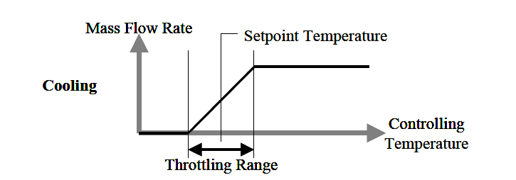
The minimum throttling range is 0.5°C.
With a chilled ceiling, there is the possibility that condensation will occur on the surface that is being cooled. This is due to the fact that the surface temperature may drop below the dew-point temperature of the space. When this occurs, condensation on the surface will occur. There are two options for handling this situation:
If you choose the 2‑Off option, EnergyPlus will not do anything other than produce a warning message when condensation is predicted to occur. The simulation will simply proceed; no moisture will be removed from the zone air and there will be no adjustment of the surface temperature as a result of the condensation. When the 1‑Simple off option is selected, EnergyPlus will predict cases where condensation will occur and shut-off the chilled ceiling to avoid this situation. With this latter option, you also have the opportunity to adjust when the system will shut down. This is specified with the Condensation Control Dew-point Offset, below.
This offset temperature (in °C or °F) is only available with the 1-Simple off condensation control type. It establishes the difference between the calculated dew-point temperature of the space and the allowed surface temperature to which the surface can drop before the chilled ceiling shuts down. This setting can be any positive, negative, or zero value. When this parameter is zero, the chilled ceiling will shut down when the surface temperature drops to the dew-point temperature or below.
When this parameter is positive, the radiant system will shut down when the surface is this value above the dew-point temperature. This allows some extra safety to avoid condensation. When this parameter is negative, the chilled ceiling will shut down when the surface temperature is this value below the dew-point temperature. While not recommended, this strategy allows the user to simulate a situation where small amounts of condensation are tolerable.
Note: This value is an offset not an absolute temperature. A typical value might be 0-2°C.
This is the schedule that determines whether or not the component is available for each hour of the simulation. A schedule value greater than 0 (usually 1 is used) indicates that the unit can be on during the hour. A value less than or equal to 0 (usually 0 is used) denotes that the unit must be off for the hour.