Advanced Calculation Options
Heating
Design, Cooling
Design and Simulation
tabs on Model Options dialog, Options tab on Simulation
Options dialog and General tab on the Heating
and Cooling Design
Calculation options dialogs.
General Solution
Solution Algorithm
This option controls the overall algorithm used for all the surfaces in the simulation apart from any that may be overriden through use of the construction Simulation solution algorithm selection for particular surfaces. Select from:
- 1-CTF - The default method used in EnergyPlus for CTF calculations
is known as the state space method (Ceylan and Myers 1980; Seem 1987;
Ouyang and Haghighat 1991). CTF is a sensible heat
only solution not taking into account moisture storage or diffusion in
the construction elements.
- 2-Finite difference
- This solution technique uses a 1-D finite difference solution in the construction elements . It is a sensible heat only solution and does not take into account moisture storage or diffusion in the construction elements. This option is required for PCM simulations and may improve accuracy for sheet metal material layers in constructions and for chilled ceilings.
- 4-Combined Heat And Moisture Finite Element (HAMT) - A coupled heat and moisture transfer and storage solution uses a one dimensional finite difference solution in the construction elements. It requires further moisture transfer property data inputs which are defined in the Moisture Transfer component.
- 5-Moisture Penetration Depth Conduction Transfer Function (EMPD) - A sensible heat diffusion and an inside surface moisture storage algorithm that also needs additional moisture material property data inputs which are defined in the Moisture Transfer component.
Allow individual constructions to override solution method
Check this option to allow Simulation solution algorithm settings made for Constructions to override the general setting above.
Finite Difference Settings
The settings below are required when the general Solution algorithm is set to 2-Finite Difference
or if any constructions used in the simulation override the general setting to use the finite difference algorithm.
Difference Scheme
This field determines the solution scheme used by the Conduction Finite Difference model. There are two options:
- 1-Fully implicit first order scheme which is first order in time and is more stable over time. But it may be slower than option 2.
- 2-Crank Nicholson 2nd order which is second order in time and may be faster than option 1 but it can be unstable over time when boundary conditions change abruptly and severely.
Space discretisation constant
The Space discretisation constant controls the how the model determines the number of nodes used to represent each material layer in the construction. The model calculates the nominal distance associated with a node, Δx , using:
Δx = (CαΔt)0.5
Where:
- α is the thermal diffusivity of the material layer, in m2/s
- Δt is the length of the timestep in seconds.
- C is a constant set by this field.
The default is 3. Typical values are from 1 to 3. Lower values for this constant lead to more nodes and finer-grained space discretisation.
Relaxation factor
The finite difference solver includes under-relaxation for improved stability for interactions with the other surfaces. This input field can optionally be used to modify the starting value for the relaxation factor. Larger numbers may solve faster, while smaller numbers may be more stable. The default is 1.0. If the program detects numerical instability, it may reduce the value entered here to something lower and more stable.
Inside face surface temperature convergence criteria
The surface heat balance model at the inside face has a numerical solver that uses a convergence parameter for a maximum allowable differences in surface temperature. This field can optionally be used to modify this convergence criteria. The default value is 0.002 and was selected for stability. Lower values may further increase stability at the expense of longer runtimes, while higher values may decrease runtimes but lead to possible instabilities. The units are °C or °F.
Airflow Network
Relative airflow convergence tolerance
The calculated natural ventilation solution is assumed to have converged when the absolute value of the sum of the mass flow rates divided by the sum of the absolute value of the mass flow rates is less than this tolerance value. The mass flow rates described here refer to the mass flow rates at all nodes in the airflow network model. The solution converges when both this tolerance and the tolerance in the Absolute airflow convergence tolerance are satisfied. The default value is 1x10⁻⁴.
Note: In cases where a large opening exists (in particular horizontal openings) this value and the absolute airflow convergence below may need to be increased by a factor of 10 or more to allow convergence to take place.
Absolute airflow convergence tolerance
The solution is assumed to have converged when the summation of the absolute value of all network airflows is less than the value specified for this input field. The default value is 1x10⁻⁶.
Convection
Inside and Outside convection algorithms
You can select from a range of EnergyPlus inside convection algorithms
for calculating the convection between internal zone surfaces and the
rest of the zone air in the simulation calculations. More details on this
and external convection can be found under Constructions
Model Data > Surface Convection
header.
Warmup
Warmup or pre-conditioning is the process of repeatedly simulating the first day before the simulation proper starts to ensure that the temperatures in the building fabric are realistic. Warmup continues until temperatures and heat flows in each zone have converged. If convergence does not occur then simulation continues for the maximum number of days as specified in the calculation option below.
 Warmup and starting simulations on a weekend
Preconditioning of the building by repeated simulation of the first day until convergence is an important part of the simulation but it can cause issues if the first day in the simulation is extreme in any way. For example if the first day in the simulation is a Sunday and the building is not heated or cooled at all on that day and extreme overheating occurs then the fabric of the will be "charged" up with heat as if those conditions had been occurring repeatedly for many days (or even weeks in some heavyweight buildings). This can mean that on the next day, the Monday the building model is far more liable to overheat than would have been the case if the simulation had started on a different day. In cases where this may be an issue, it may be worth starting simulations on the first occupied day rather than on a weekend day.
Maximum number of warmup days (not heating/cooling
design)
The maximum number of "warmup" or pre-conditioning days that can be used in the simulation
before the simulation proper starts. A warning message will occur when the warmup
simulation does not converge in the allowed maximum number of warmup days:
Loads Initialization
did not Converge (CheckWarmupConvergence)
This error is usually caused by using very thick constructions (e.g. ground floors). You may need to increase the Maximum number of warmup days to get
convergence, but some anomalous buildings may still not converge.
See also Temperature
and loads convergence below.
Minimum number of warmup days (not heating/cooling
design)
This data specifies the minimum number of “warmup” days before EnergyPlus will check if it has achieved convergence and can thus start running the simulation proper.
Value to use
Research into the minimum number of warmup days indicates that 6 warmup days is generally enough on the minimum end of the spectrum to avoid false predictions of convergence and thus to produce enough temperature and flux history to start EnergyPlus simulation. This was based on a study that used a set of benchmark reference buildings. It also was observed that convergence performance improved when the number of warmup days increased. As a result, the default value for the minimum warmup days has been set to 6. You should decrease this number only if you have knowledge that a specific model converges more quickly than 6 days. You may wish to increase the value in certain situations when, based on review of simulation outputs, it is determined that EnergyPlus has not converged. While this parameter should be less than the previous parameter, a value greater than the value entered in the field Maximum number of warmup days above may be used when users wish to increase warmup days more than the previous maximum number of days. In this particular case, the maximum value will be automatically reset to the value entered here and EnergyPlus will run exactly the number of warmup days specified here.
See also Temperature
and loads convergence below.
Temperature and loads convergence
The temperature and loads convergence values represent the maximum allowable difference
in zone temperature and loads between successive daily iterations before convergence
is considered to have been reached during warmup.
Convergence of the simultaneous heat balance/HVAC solution is reached
when both the loads and temperature criteria are satisfied. Both tolerances
work the same way, one looks at temperatures and one looks at heating
and cooling loads. After the second warm-up day, the program compares
the maximum temperature experienced in a space with the maximum temperature
from the previous day. If those two temperatures are within the tolerance,
then it has passed the first warm-up check. It does a similar comparison
with lowest temperatures experience within all the zones. If the current
simulation day and the previous day values are within the tolerance, then
it has passed the second warm-up check. A similar comparison is carried out
with the loads tolerance and the maximum heating and cooling loads that
are experienced within the spaces. Those are compared individually to
the values for the previous day. If they are both in tolerance, then the
simulation has passed the third and fourth warm-up check. The simulation
stays in the warm-up period until ALL FOUR checks have been passed.
Note: The maximum number of warmup days will override the above convergence criteria, i.e. the simulation proper will start even if convergence has not occurred after the maximum number of warmup days.
Shading
Maximum number of shadow overlaps (not heating
design)
Enter the maximum number of figures per shadow overlap. The shadow overlaps
is a measure of the amount of complexity in the shading calculation and
this maximum value allows you to limit the amount of time spent in the
solar initialisation calculations.
Note: entering
a small value here can speed up simulations in complex buildings. If you
plan to use Maximum shadow overlaps below
the default value of 15000 you should check accuracy of solar gains relative
to results using default value
Polygon clipping algorithm
This is an advanced feature. Prior to V7, the internal polygon clipping method was a special case of the Weiler-Atherton method. Now, two options are available:
- 1-Sutherland Hodgman (default)
- 2-Convex Weiler Atherton
Theoretically, Sutherland-Hodgman is a simpler algorithm but it works well in cases where receiving surfaces (of shadows) are non-convex. The Weiler-Atherton implementation is only accurate where both casting and receiving surfaces are convex. Warnings/severe errors are displayed when necessary. More details on polygon clipping are contained in the Engineering Reference.
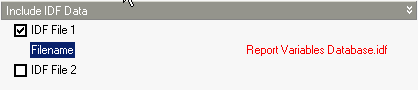
Include IDF Data (not heating/cooling
design)
You can include up to 2 custom IDF data in your EnergyPlus simulations
by checking the IDF File 1 or IDF
File 2 check boxes and entering the name of the IDF data source
file. The contents of any files specified are copied to the end of the
IDF data generated by DesignBuilder before simulation. This can be a useful way to add in extra output reports, simulation objects etc, that do not interfere with the main IDF data.
For example if you needed to access output reports data not normally provided by DesignBuilder such as "Time Heating Setpoint Not Met While Occupied" then you might save a small IDF file in the DesignBuilder EnergyPlus
folder called Reports Variables Database.idf containing this data:
Output:Variable, *, Time Heating Setpoint Not Met While Occupied, monthly;
Output:Variable, *, Time Cooling Setpoint Not Met While Occupied, monthly;
The file must be selected on this dialog as shown below.
After the simulation is finished the above setpoint not met monthly data would be included in the eso file which can be viewed outside DesignBuilder to obtain the extra outputs.
Note: Included
IDF files must be located in the EnergyPlus
folder.
Note: A more flexible way to include IDF is available through the EMS system. EMS includes the IDF data within the dsb file so it is more portable. Also you can store and manage a list of various IDF datasets with EMS which makes it easier to switch various models and/or outputs in and out very easily.
Other
Surfaces within zone treated as adiabatic
EnergyPlus support recommend modelling surfaces wholly contained within
a zone as adiabatic and this option allows you to follow this advice.
We have found that in practice this option does not make much difference in
results or in simulation speed so for most cases you can leave it in its
default state.
See also EnergyPlus Errors and Warnings
Note: 'surfaces
contained within a zone' are frequently generated when one of the zone
merging options is used where a partition or floor which would have
separated two zones actually sits within the merged zone. These surfaces
do not refer to hanging
partitions which are modelled using Internal
thermal mass.
Air velocity for comfort calculations
The thermal comfort calculations carried out by EnergyPlus to obtain the comfort outputs require the velocity of the air close to the occupants . Enter this air velocity here (in m/s or ft/min). The default air velocity is 0.137 m/s, but higher values might be appropriate for rooms with mixing fans or high volumes of HVAC air delivery, for example.