Construction layer data
Layers tab on Constructions
Dialog.
Definition
You can select the way you would like to define the construction. The options depend on whether you are using EnergyPlus or SBEM Analysis type and whether it is a construction from the Floor (ground) or Below grade wall categories.
For EnergyPlus the allowable definition methods are:
- 1-Layers where the construction is defined by specifying layers each having a material and thickness.
- 5-C-factor when the category is Below grade wall
- 6-F-factor when the category is Floor (ground)
Calculation Settings
 Simulation solution algorithm
Some constructions may need a particular solution algorithm to obtain most realistic results. For example PCMs require a finite difference solution. However simulations may run slowly if all surfaces are simulated using the finite difference solution method. This option allows you to override the overall simulation solution algorithm for any surfaces using this construction.
Options are:
- 1-Default where surfaces using this construction receives no special treatment and is simulated using the default solution algorithm.
- 2-CTF where surfaces using this construction are simulated using the CTF algorithm regardless of the general solution method selected.
- 3-Finite difference where surfaces using this construction are simulated using the finite difference algorithm regardless of the general solution method selected.
- 4-HAMT where surfaces using this construction are simulated using the Combined Heat And Moisture Finite Element (HAMT) solution method. This coupled heat and moisture transfer and storage solution uses a one dimensional finite difference solution in the construction elements. It requires further moisture transfer properties which are defined in the Moisture Transfer component.
- 5-EMPD where surfaces using this construction are simulated using the Moisture Penetration Depth Conduction Transfer Function (EMPD) solution method. This sensible heat diffusion and an inside surface moisture storage algorithm also needs additional moisture material property information defined in the Moisture Transfer component.
You may wish to use this option to select the 2-Finite difference option for constructions which have one or more of:
- Phase change materials (PCMs) - these can be simulated with the CTF option but the phase change characteristics will be ignored so any construction using PCMs would normally have the 3-Finite difference option set.
- We understand that Detailed HVAC Chilled ceilings may benefit from use of the finite difference algorithm.
- Constructions using thin sheets of metal may not be treated accurately by the default CTF algorithm and for most accurate treatment you may wish to use finite difference for such constructions.
Bear in mind that the simulation times will increase when using the finite difference option even for just a few surfaces. If you are in doubt, you may find it worthwhile experimenting with the 2 solution methods, comparing hourly results, to see the effect of changes. Depending on the case, it may or may not be worth the extra simulation time required by the finite difference option.
Note 1: Any settings made here will only take effect if the Allow individual constructions to override solution method model option is checked.
Note 2: This setting only applies to simulations. Heating and Cooling design calculations use the CTF algorithm for all surfaces.
Includes metal cladding
If the construction can be defined as a metal cladding system then you should check this option. This option affects linear thermal bridging at junctions involving surfaces made up of this construction.
Definition of Metal cladding
Constructions involving metal cladding are roof or wall systems where metal forms an integral part of the construction, such as metal twin skin systems where the insulation is located between the metal skins and where the metal skins are typically in the range 0.4 mm to 1.2 mm. Cladding with z-spacers would come into this category as would composite metal panel systems.
If the metal is simply used as an external shield against weather, such as a rainscreen, this is not classed, for the purposes of calculations as "metal cladding".
Metal cladding systems are divided into two broad categories, these being:
- built up metal cladding systems involving rail and bracket or z-spacer systems with insulation within the panels
- composite panel metal cladding systems with insulation inside the panels
Layers
Set the number of layers first, then select the material and thickness
for each layer. Use the Controls in the Info Panel to insert and delete
layers. For
example to delete a layer, first click on the material for the layer to
identify which layer you want to delete, then click on Delete layer.
You can create constructions with up to 10 layers.
Note: You should not include surface resistance
(film coefficient) layers to represent the resistance of the air films
adjacent to the inner and outer surfaces. These are included
automatically by DesignBuilder.
Layer order
You should define the layers in the same order they appear in the actual
construction starting with the outermost layer and finishing with the
innermost. The outermost layer will be positioned adjacent to outside
(or in the case of Semi-exposed walls)
adjacent to the Semi-exterior unconditioned
zone.
For interior partition surfaces the order of the layers is not defined directly from the usage of the construction in a surface, so in this case the layer order is determined through a series of checks to see which zone is relatively ‘more external’. For example, if one zone is unconditioned and the other not then the partition layers are ordered so that the outermost layer is next to the unconditioned zone. When both zones are occupied, a similar check is made using heating and cooling setpoint temperatures. If after all these checks the zones are still both equally ‘internal’ then the direction of the layers will be set up in an arbitrary way.
Tip: When modelling an asymmetric partition between 2 zones that have identical zone type and heating and cooling setpoints and you need to specify the exact order of the partition layers, you can make a small difference in heating or cooling setpoint temperature between the 2 zones. For example, consider the case of an occupied atrium zone adjacent to an office zone and the partition between the 2 has a thermal mass layer that must be adjacent to the atrium. This situation could be modelled for example by setting the heating setpoint of the atrium to be 0.1°C lower than the office (or if the heating setpoints are the same then the cooling setpoint could be set 0.1°C higher) and by making the thermal mass layer to be the outermost layer in the construction layer definition.
Detailed description of asymmetric partition layer order algorithm
DesignBuilder sets up the layer order for asymmetric partitions such that the outermost layer is next to the zone which it considers to be the more "external" of the two zone. The method used to decide which of the zones is relatively more external is as follows:
Step 1. Check whether zones are heated or not (Heating checkbox on the HVAC tab).
- If only one zone has heating switched on then the outermost layer is set to be next to the unheated zone.
- If both zones are heated then the Heating setpoint temperatures are checked for both zones. The zone with the lower heating temperature setpoint is considered to be the most external and the outermost layer is set next to it.
- If both zones are heated and have the same heating setpoint temperature then go to Step 2.
- If both zones are unheated then go to Step 2.
Step 2. Check whether cooling is active in the zones (Cooling checkbox on the HVAC tab).
- If only one zone has cooling switched on then the outermost layer is set to be next to the uncooled zone.
- If both zones are cooled then the Cooling setpoint temperatures are checked for both zones. The zone with the higher cooling setpoint temperature is considered to be the most external and the outermost layer is set next to it.
- If both zones are cooled and have the same cooling setpoint temperature then go to Step 3.
- If both zones don't have cooling then go to Step 3.
Step 3. Both zones are considered to be "equally external" and the direction of the layers are set up in an arbitrary way.
Note: The above checks are carried out before the simulation starts and scheduled setpoint values are not used. The setpoints referred to above are the "headline" setpoint values entered under the Environmental control header on the Activity tab.
Thickness
This field characterizes the thickness of the material layer. This is
the dimension of the layer in the direction perpendicular to the main
path of heat conduction.
Note: Modelling layers thinner (less) than 0.003 m is not normally recommended; rather, add those properties to one of the adjacent layers.
If the material referenced is defined as a simple
R-value then the layer thickness does not affect the thermal performance of the construction.
If the material is defined as having a fixed thickness then the layer thickness is loaded automatically when the material is selected and the thickness does not have to be entered and cannot be edited.
Photovoltaic Panel
When the Building Integrated Photovoltaics Construction category is selected, you can define the properties of a BIPV panel below the data for the outermost layer.
Tip: See Photovoltaic (PV) Systems for a description of the process involved in modelling BIPV systems.
Performance type
Select from:
- 1-Simple, and
- 2-Equivalent One-Diode.
Depending on the selection you will be able to select from either a simple or equivalent one-diode definition of the panel.
Tip: BIPV panels are included in the electrical generation side of the model by specifying them on the Generator list tab of the Electric load centre dialog when one of the d.c. Buss types is selected.
Performance model
Choose the component to be used to define the performance of the collector. When the 1-Simple performance type is selected, select from the list of previously defined Simple Photovoltaic components, or when 2-Equivalent One-Diode is selected then choose from one of the Equivalent One-Diode components.
Heat transfer integration mode
The PV model allows for different ways of integrating with other EnergyPlus heat transfer surfaces and models and calculating cell temperature. Choose from:
To model PV panels that are integrated in some way with the underlying construction, choose one of the integrated heat transfer mode options. Otherwise, the decoupled options will have a similar effect as drawing a separate PV panel on top of the surface at building level.
Modules in parallel
This field is the number of series-wired strings of PV modules that are in parallel to form the PV array. The product of this field and the next field should equal the total number of modules in the array.
The Modules in parallel and Modules in series data are only used for 2-Equivalent One-Diode PV arrays.
Modules in series
This field is the number of modules wired in series (on each string) to form the PV array. The product of this field and the previous field should equal the total number of modules in the array.
Bridging
You can add repeating thermal bridging to any layer to model the effect of a relatively
more conductive material bridging a less conductive material. For
example wooden joists bridging an insulation layer.
Note: bridging
effects are not yet used directly in EnergyPlus, but are used in energy code compliance
checks requiring U-values to be calculated according to BS EN ISO 6946. However see below for a workaround to this limitation.
Method for approximating repeating bridging effects in simulations
Although EnergyPlus cannot allow repeating bridging directly in simulations it is possible to approximate the effect of bridging by adjusting the thickness of the insulation to a value that gives the same U-value as the bridged construction calculated using BS EN ISO 6946. This is easily achieved by following these steps:
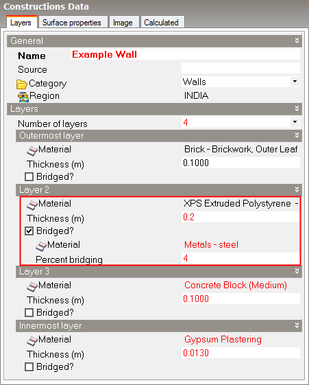
- Define the construction including bridging data as in the screenshot below.
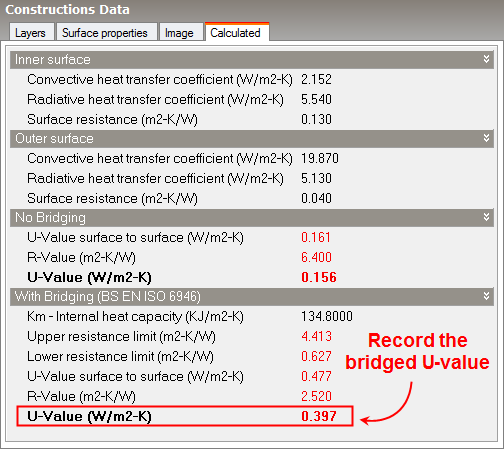
- Note the construction bridged U-value on the Calculated tab, see below.
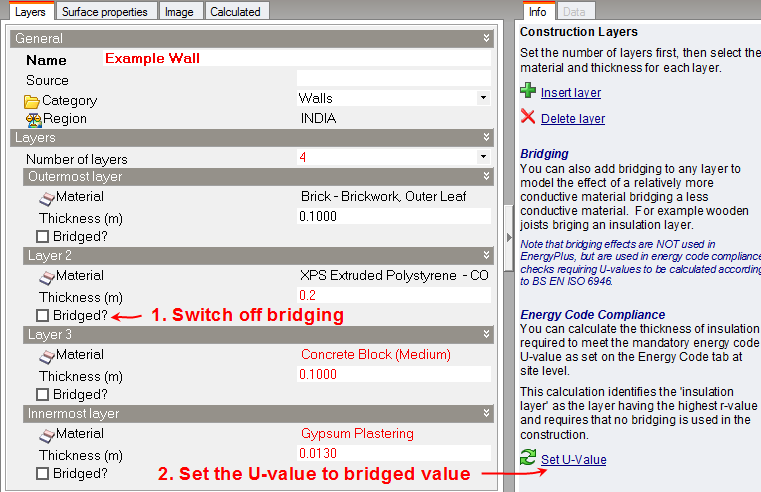
- Going back to the layers tab, switch off all bridging and set the U-value to the bridged U-value by clicking on the Set U-value link in the Info panel.
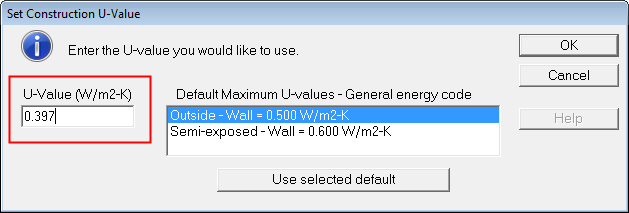
- Enter the recorded bridged U-value (0.397 W/m2-K in this case) on the dialog and press OK.
- Confirm the reduced insulation thickness when prompted.
- Check the new insulation thickness and U-value of the construction. The insulation thickness should be reduced as per the pop up message and the U-value should be the same as the bridged value you recorded earlier. The construction should now behave in a very similar way to the bridged construction in heating and cooling design calculations and in simulations.