 More information on component blocks can be found in the Basic Drawing Tools 8 Tutorial
There are 3 types of component block:
Component blocks are drawn in the same way as Building blocks but selecting the Block type in the Drawing Options panel to be 3-Component block.
Each Component block has its own Component block material, transmittance schedule and shade/not shade model data. To edit this you must first go to the component block itself by double-clicking on it in the model edit screen or clicking on the entry in the Navigator. Alternatively, component blocks inherit default model data from the building level so if you leave the component block model data in its default state (blue) you can change all model data in one go by making the edit at the building level.
All component blocks cast shadows in Visualisations. In Radiance daylighting calculations component blocks both cast shadows and provide diffuse and/or specular reflection.
More information on component blocks can be found in the Basic Drawing Tools 8 Tutorial
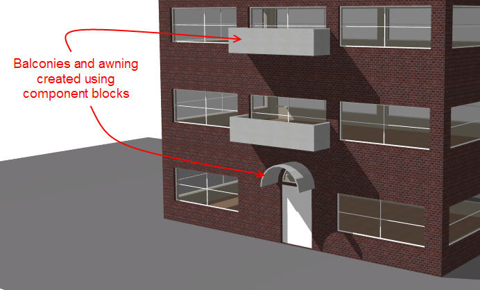
Sometimes it can be useful to create structures such as pillars, shading obstructions and balconies which do not contain zones. Standard component blocks can be used for modelling such structures as they are treated simply as shading/reflection surfaces in simulations without any zones.
Standard component blocks are visible in Visualisations, using the texture associated with the Component block material as set on the Constructions tab under the Component Block header. They can be used to cast shadows and reflect solar radiation and light in EnergyPlus simulations by checking the Component block shades and reflects model data under Component Blocks on the Constructions tab.
Note: In EnergyPlus simulations, component blocks do not shade ground reflected solar radiation and light unless the Model reflections and shading of ground reflected solar calculation option is used.
The image below shows some typical uses of Standard component blocks.
Important Note: Component blocks do not absorb or conduct heat in any way - their only effect on building surfaces in simulations is related to the shading and reflection of short-wave solar radiation and light.
Component blocks are a flexible way to apply shading to any part of the building and can be used to model more complex window shading systems not catered for by the in-built local shading systems that can be selected on the Openings tab. However there are some issues that should be considered when using component block in this way and these are discussed in the Component blocks used for local shading reference page.
Note: Standard component blocks can be added at building and block levels, but component blocks added at block level are not used in EnergyPlus simulations. They are however used in CFD, Daylighting and Visualisation.
Use of standard component blocks for shading is also covered in the Solar Shading Tutorial
Ground component blocks can be used as a convenient way to set the adjacency of any touching building block surfaces as being 'adjacent to ground'. In the model below the Ground block (shown in green) has been positioned in contact with the building block to create a ground adjacency in the part of the Building block surface in contact with the Ground block.
Ground component blocks are visible in Visualisations, using the texture associated with the Component block material as set on the Constructions tab under the Component Block header. They can be used to cast shadows and reflect solar radiation and light in simulations by checking the Component block shades and reflects model data under Component Blocks on the Constructions tab.
Note: It is important to understand that the ground component block is used only to modify the adjacency of the surfaces touching it to be 'adjacent to ground'. The areas of the zone surfaces that do touch the ground component block are treated as being adjacent to the monthly ground temperatures defined for the site. The material associated with the ground component block and the thickness of the block are not used in any way to modify the conduction path of heat from the building to the ground. To modify the properties of the ground heat transfer, edit the ground construction.
Surfaces with any openings which touch a ground component block will have those openings removed when the component block is placed. Also it is not be possible to add openings in parts of a zone surface that touch a ground component block. This applies to sub-surfaces as well as windows, doors, vents and holes.
View from building level
View from zone level
Ground component blocks are displayed in the visualisation screen using the Ground texture as set at the site level.
More information on ground modelling can be found in the Ground Modelling topic.
Note: The adjacencies established by contact with ground blocks can be overridden by making settings under Adjacency in Constructions model data at the surface level.
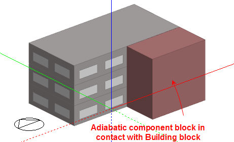
Adiabatic component blocks can be used as a convenient way to set the adjacency of any touching building block surfaces to 'adiabatic'. Adiabatic surfaces do not transfer heat beyond their outer surface and are often used for modelling boundaries with other spaces that can be considered to be at roughly the same temperature as the zone. In the model below the Adiabatic block (shown in red) has been positioned in contact with half of the South facade of the building to model the effect of an adjacent building which does not form part of the DesignBuilder model. The touching adiabatic component block creates an adiabatic adjacency in the part of the Building block surface in contact with the Adiabatic block.
Adiabatic component blocks are visible in Visualisations, using the texture associated with the Component block material as set on the Constructions tab under the Component Block header. They can be used to cast shadows and reflect solar radiation and light in simulations by checking the Component block shades and reflects model data under Component Blocks on the Constructions tab.
View from building level
View from zone level
Note: While no heat is conducted across the outer side of adiabatic surfaces, these surface will still allow the flow of heat at the inside surface into the structure and so act to provide thermal mass to the connected zone. Therefore simulation results will show heat transfer for adiabatic surfaces. In thermally massive constructions (e.g. concrete floors) these heat flows can be quite significant over the period of hours and days,but usually less so over monthly intervals.
Note: All openings and sub-surfaces in adiabatic surfaces are ignored in EnergyPlus simulations