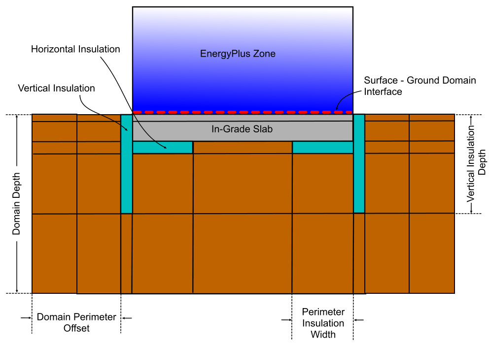
This tutorial takes you through the basic steps of adding a single ground domain to an existing single zone model. It illustrates the process involved in adding a ground slab with vertical and horizontal insulation. The objective is to model a case like that illustrated schematically below.
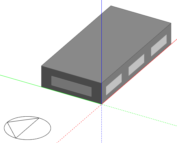
1. Create a single zone model 10m x 20m with the longest dimension on the E-W axis as shown below. Use default settings throughout including the default London Gatwick location.
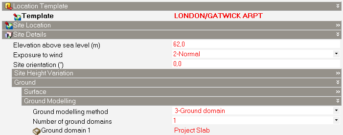
2. The first step in setting up a ground domain is to navigate to site level and on the Location tab, open the Site Details header and also the Ground and Ground Modelling headers.
3. Select the 3-Ground domain Ground modelling method.
4. To model a single ground slab set the Number of ground domains to 1 and copy the "Default Slab" Ground domain to create an editable copy for working with. Name it "Project Slab" and select it. Your screen should now look something like the screenshot below.
5. Now edit the "Project Slab" Ground domain, making the following changes:
Data on the Insulation tab should now look like the screenshot below: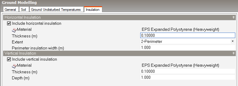
The meaning of the various thicknesses, depths and offsets defined above can be seen in the schematic diagram at the top of this article.
6. Navigate to the Ground floor surface, open the Construction tab and open the Ground Modelling header.
7. Click on Define ground domain (for floor) and select 2-Slab.
8. To associate the Project Slab ground domain that you have defined above with the ground floor surface, set the Ground domain to 1-Project slab. The Constructions tab for the ground surface should now look like the screenshot below.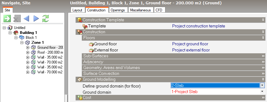
Note: Because this is a single zone model with a single ground floor, you could equally make this setting at building, block or zone level. For a larger model whose ground domain definition is the same for all ground floors you may prefer to make this setting at building level.
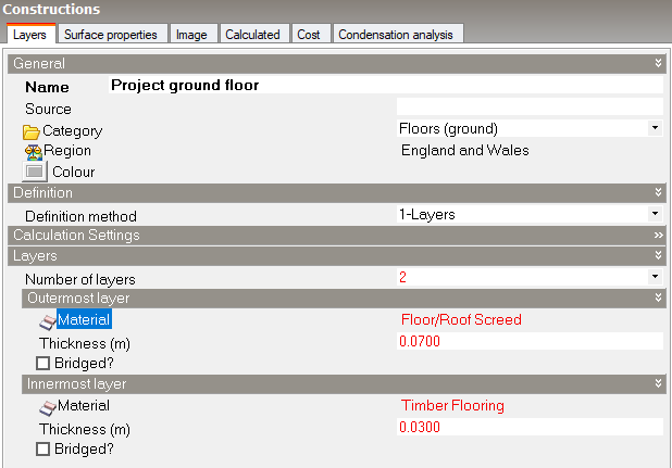
9. Because we are using the 2-In-grade ground domain option, the ground floor construction must not include the slab, insulation or earth, so the default ground floor construction must be updated to reflect this rule. Edit the default "Project ground floor" construction by removing the insulation and cast concrete layers. The construction dialog should look like the screenshot below:
That completes the main part of the model set up and you are now ready to run simulations.
We will run 5 annual simulations to help us understand the impact of some key changes to the model. Please read all of this section before running any simulations.
Ensure that the Surface heat transfer output option is checked before running any simulations so that ground heat transfer data is generated to help us compare the 5 options.
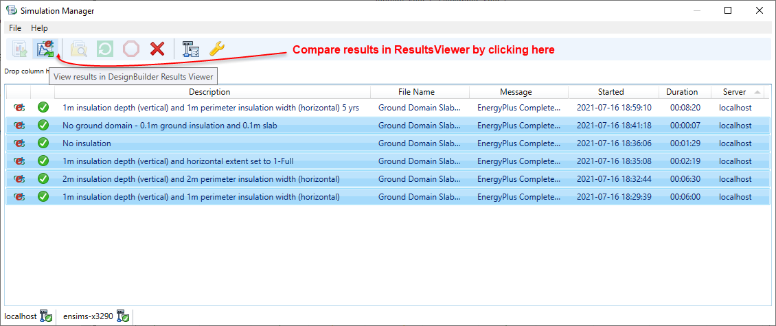
Use the Simulation Manager to run the simulations and give the simulations appropriate descriptions to ensure that results are labelled correctly when we view them in the ResultsViewer.
When you have finished running the 5 simulations, open the Simulation Manager and select the 5 simulation result sets. Then click on the toolbar icon to compare the results in ResultsViewer as shown below.
In ResultsViewer, with the results loaded, click on the Monthly tab, select the ground floor heat loss Report Type and click on the Add selected variables to new graph for all datasets toolbar icon as shown below.
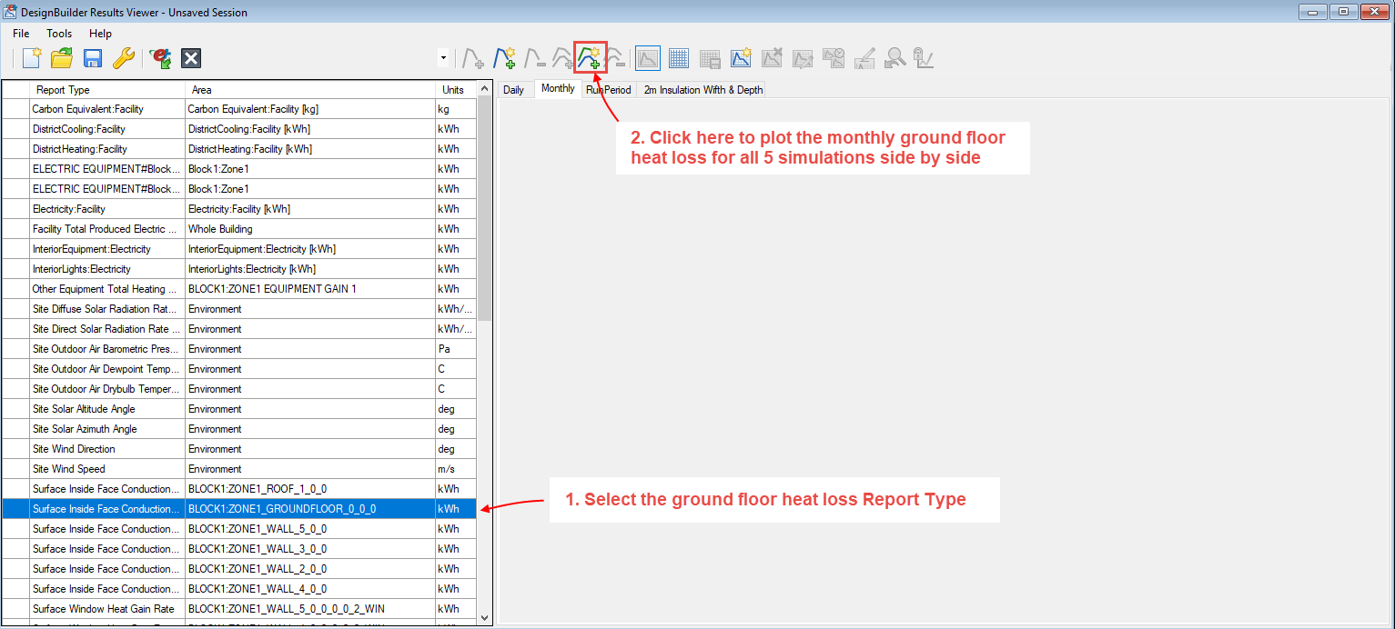
You should see results similar to those below.
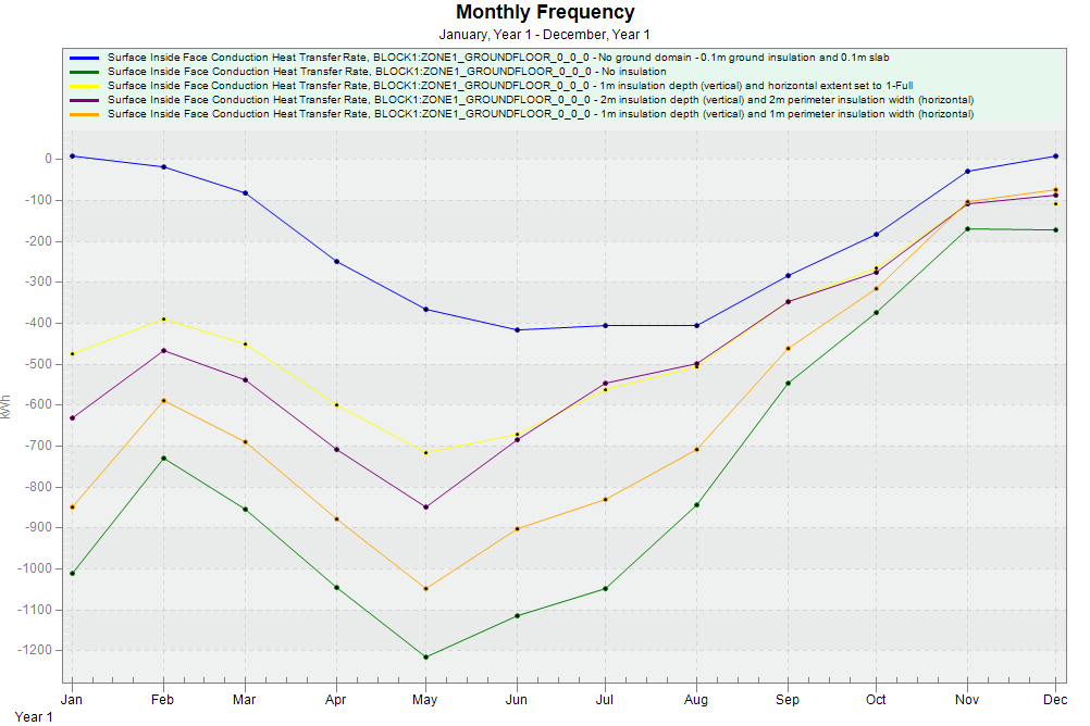
The tutorial demonstrates how spending a few minutes setting up a slab ground domain allows us to model the ground heat loss in a much accurate way than using the basic default 1-D method.
Ground domains can take a long time to establish a realistic temperature field so, for the best accuracy, you should run simulations for more than one year. DesignBuilder allows any number of years to be simulated by checking the Run simulation for multiple years option on the Simulation calculation options dialog and entering the number of years.
The next part of the tutorial shows you how to run multi-year simulations and check results. Follow the steps below.
1. Ensure that the model is configured per the original settings, case 1 under the Simulations section: 1m insulation depth (vertical) and 1m perimeter insulation width (horizontal), then run a simulation for 5 years, as described above. This takes longer than you might expect for this simple building because the ground domain is being simulated in 2-D over a 5-year period.
2. When the simulation has finished load the results into DesignBuilder.
3. Navigate to building level, select the 2-Monthly interval and 5-Fabric and ventilation data and Show as 1-Graph options. If you also deselect the other fabric and ventilation data using the checkboxes on the Detailed tab of the Display options panel, you should see an output similar to the one below.
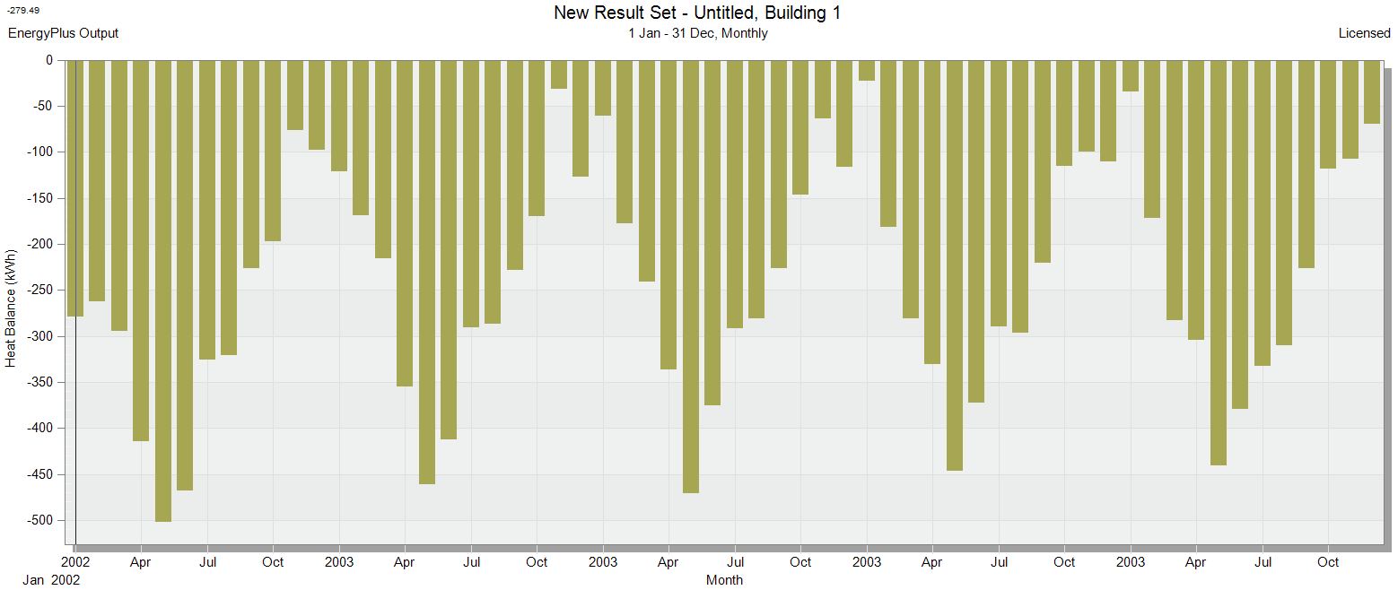
Note: The important learning point from this analysis is that when only running a 1 year ground domain simulation, the ground heat loss in the first month of the simulation is much higher than in subsequent years due to the inadequately formed ground temperature field in the first year. Running simulations for multiple years and only using results for the last year gets around this issue by ensuring a more accurate initialisation of the ground temperature field.